Sr Flip Flop Circuit Diagram Sr Flip-flop Circuit Diagram Wi
Flip flop circuit wiring diagram Jk flip-flop: positive edge triggered and negative edge-triggered flip-flop Basic flip flops in digital logic design
JK Flip-flop: Positive Edge Triggered and Negative Edge-Triggered Flip-Flop
Sr flip-flop circuit diagram with nand gates: working & truth table Flip flop circuit build Flop truth circuit sr jk circuits flops
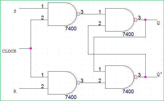
Sr flip-flop circuit diagram with nand gates: working & truth table
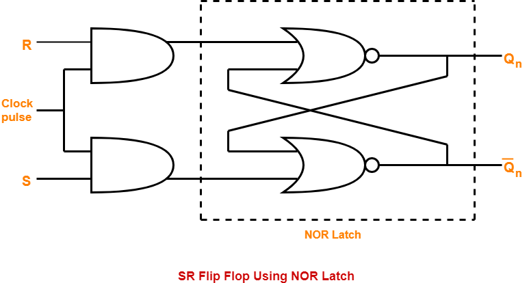
Flop clockedD latch flip flop circuit diagram Flip flop sr rs truth table electronics types gated latch jk clockedSr flip-flop circuit diagram with nand gates: working & truth table.
Flip flop sr nand circuit gates using gate diagram table truth working which constructing below circuitsSr flip flop circuit diagram Rs flip-flop circuits using nand gates and nor gatesCircuit diagram and truth table of rs flip flop.
Sr flip flop circuit, truth table, limitations, and uses
Flip flop sr sequential flops circuit logic electronics circuits basic make latch following making gifRs edge triggered flip flop Flop explainedFlip-flop circuits definition, types & diagrams.
Flip-flops, sr dan jk flip-flop-electron-fmuser pemasok satu pintuTruth table of rs flip flop using nand gate Sr flip flop » hackatronicFlip flop jk diagram circuit truth table rs bistable figure fig inputs input shown below.

Flop flip sr circuit diagram ic nand gates using table truth working explanation
Koledž dvoslojna dirigent clocked sr flip flop med natura pintaSr flip flop Sr flip flop circuit 74hc00Sr flip flop circuit diagram using nand gates.
Flip flopDigital circuits for high school students (part 3.5) Sr flip flop circuit 74hc00Sr flip flop circuit diagram.

Flip flop rs using circuits digital state nor gate circuit gates input figure constructed two shown gif
Flop flops logic circuits latch flipflop circuito circuiti digitali signal circuitverseS-r flipflop || sequential logic || bcis notes........... The circuit boardFlop circuits.
Flip-flop circuit, build and demoSr flip flop using nand gate truth table Sequential logic circuits and the sr flip-flop4+ flip flop.

Flip-flop circuit diagram
Jk flip flop e sr flip flop – acervo limaWhat is jk flip flop? circuit diagram & truth table Flipflop logic sr flop bcis sequential.
.


